MAC Formula Electric · McMaster University · FSAE

LV Electronics Lead
designing the brain
of a race car.

Formula SAE is an annual international competition where university students design, build, and race formula-style cars. As LV Electronics Lead at MAC Formula Electric, I design the Electronic Control Units the PCBs that make the car run.

2024–25 Season Overview

Re-spinning three ECUs.
Shrinking. Simplifying. Shipping.

Every season the electrical leads push to better improve the electrical system of the car. My job as LV Electronics Lead is to design, manufacture, and test the Electronic Control Units (ECUs) which come in the form of PCBs, designed entirely by my sub-team of 6 and I.

For 2024–25, I am re-spinning the LV Controller, Front Controller, and Raspberry Pi Hat boards. The core changes involve shrinking the boards, adding sensor support requested by the mechanical team, and implementing CAN Flash allowing software to be flashed to all STM32 microcontrollers through a single connection point.

Altium DesignerSTM32CAN FlashPCB DesignLV Electronics4-layer PCB
PCB Development Workflow
01Block diagram requirements + outputs
02Connector table signal routing per connector
03Schematic design in Altium
04Schematic review with leads
05PCB layout + routing
06PCB design review
07Order components + board
08In-house manufacture & assembly
09Test & validate
10Install on testbench or in vehicle
PCB Projects

Three boards. One car.

Every board is designed by my sub-team from schematic to final manufactured PCB. Click any board to see what it does and what changed this season.

Back of vehicle behind driver
LV Controller Rev3

The LV Controller is the ECU responsible for managing startup of the LV system, housing control for sensors, vehicle lights, shutdown circuitry, and more.

FUNCTIONS
  • Communication to LV BMS + current monitoring
  • HV DCDC control
  • PWM control of pumps and radiator fans
  • Shutdown circuit connections (motor interlocks, roll hoop button)
  • Ready-to-Move (RTM) light + TSSI (software)
  • Powering IMU, GPS, Raspberry Pi, and other sensors
LV Controller Rev3
KEY CHANGES THIS SEASON
Power system redesign
Replaced complicated power multiplexer with an ideal diode controller enabling LV battery startup + DCDC charging in a much simpler circuit.
CAN Flash support
Added CAN flash pins to STM32 so all boards can be flashed over a single CAN connection no more removing boards from enclosures.
RTM strobing circuit
New FSAE rule requires a "Ready to Move" light flashing 2–5 Hz. Implemented with a 555 timer (hardwired, no software) + HSD to step up to 12V.
Debug LEDs on all power rails
LEDs on 3.3V, 5V, 12V, 24V rails and CAN lines makes bench testing dramatically faster.
Added two powertrain pump channels
Extra HSD channels for accumulator cooling pumps, and split fan control into individual channels.
Altium DesignerSTM32HSD (High-Side Drivers)CAN Transceiver555 TimerIdeal Diode Controller (LM74700)
Front of vehicle behind dashboard
Front Controller Rev3
Front of vehicle behind pedals
Raspberry Pi Hat
Technical Deep Dive

LV Power Circuitry Redesign

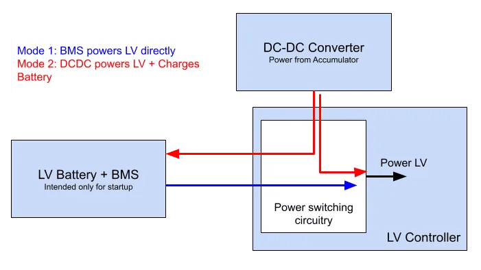
The most significant change this season. The old LV controller used an external battery pack with a complicated power multiplexer. This year we're moving to a custom LV battery which means current needs to flow back into the battery for charging. That changes everything about the power topology.

THE PROBLEM

The existing power multiplexer chose between battery and DCDC power but it only allowed current to flow out of the battery. With a custom LV battery + BMS, we need current to flow back in for charging too.

THE SOLUTION

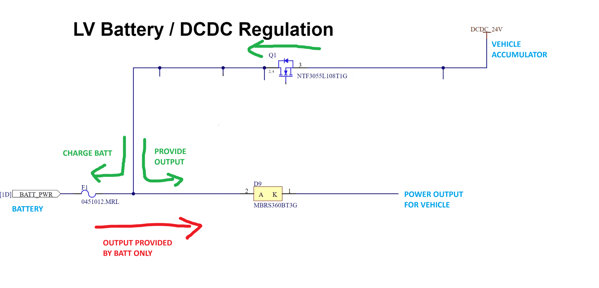
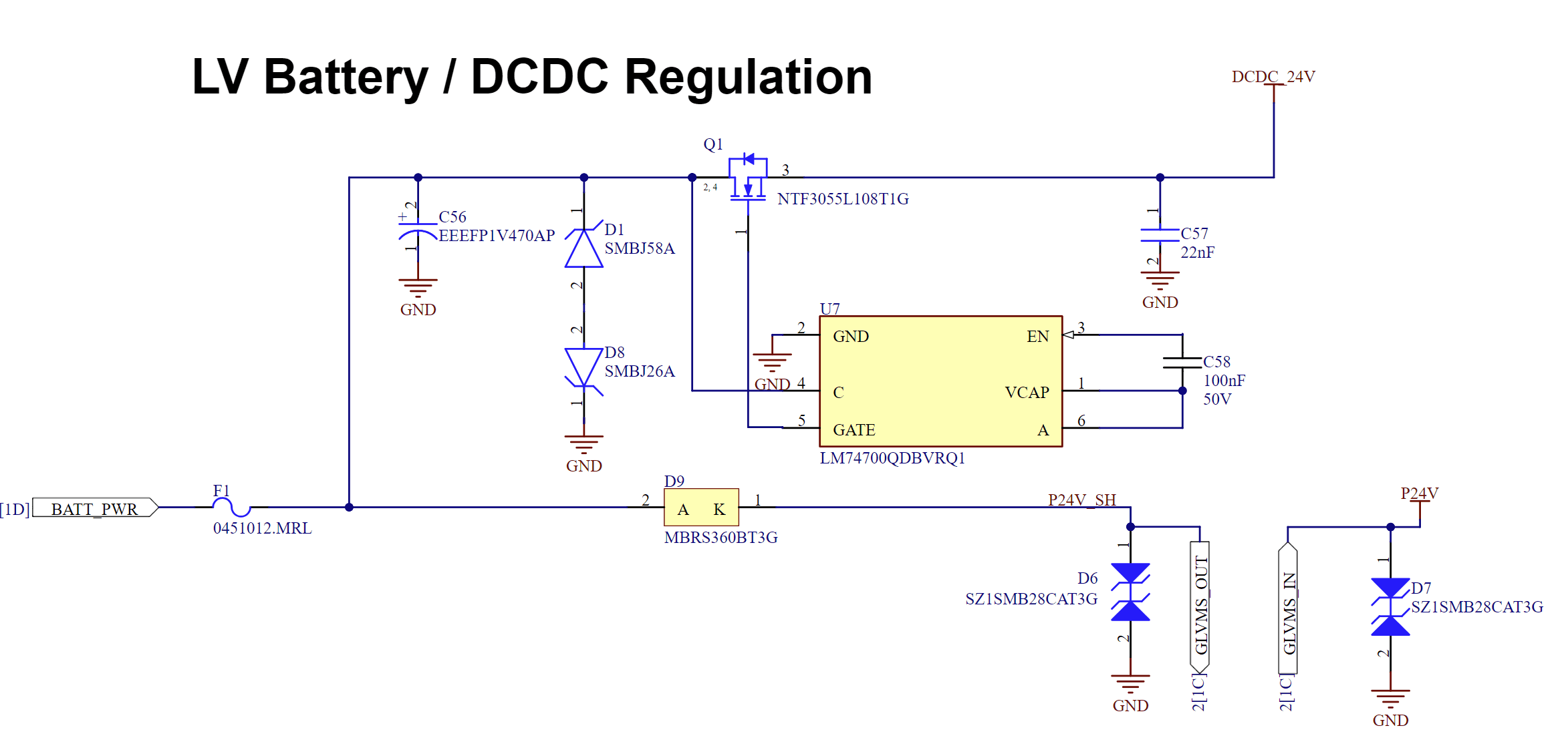
An ideal diode controller (LM74700) a MOSFET-based circuit that mimics a diode with near-zero voltage drop. Battery powers startup; when DCDC turns on at higher potential, it automatically powers the LV system and charges the battery. No software. No switches. Just physics.

TEST RESULTS IDEAL DIODE VALIDATION
Batt_PWR active → DCDC_24V
Expected: 0V
Measured: 0.16V
PASS ✓
DCDC_24V active → Batt_PWR
Expected: 24V
Measured: 23.98V
PASS ✓
DCDC charges battery when active
Expected: YES
Measured: CONFIRMED
PASS ✓
CIRCUIT DIAGRAMS click to enlarge
Problem: LV battery must startup the car, then DCDC must charge it back
New charge/discharge paths using ideal diode controller
Final simplified circuit  massive reduction in component count
Final simplified circuit massive reduction in component count
Vehicle Electrical Architecture

How it all fits together

The three PCBs are nodes in a broader electrical architecture that the LV team has been developing over several seasons. The LV Controller, Front Controller, and RPi Hat all communicate over two separate CAN buses Vehicle CAN and Powertrain CAN.

Rear
LV Controller
Startup sequencing, power management, cooling pumps, fans, sensors
Front
Front Controller
Safety circuits, pedal/steering sensing, torque control, two CAN buses
Front
Raspberry Pi Hat
Telemetry logging, CAN Flash gateway for all STM32 boards
Rear
Orion BMS
Battery management system, cell monitoring, state-of-charge over CAN
Rear
Motor Controllers
Receive torque requests from Front Controller over Powertrain CAN
Front
Dashboard
Driver display speed, mode, warnings. Communicates over Vehicle CAN